Topic 2, Contoso Case Study 2

You have an Azure subscription that contains the resources shown in the following table.


You need to ensure that you can integrate WebApp1 and Vnet1.

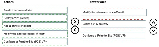
Which three actions should you perform in sequence before you can integrate WebApp1 and Vnet1? To answer, move the appropriate actions from the list of actions to the answer area and arrange them in the correct order.


Explanation:
Azure App Service regional VNet Integration requires the virtual network to be in the same region as the web app. WebApp1 is in West US, but VNet1 is in East US with address space 10.3.0.0/16 and a single subnet Subnet1 using the entire /16 range. To enable integration, you must first modify the address space to create a dedicated subnet for integration, create the subnet, and then configure integration. VNet peering is not possible across regions for App Service VNet Integration. VPN gateway and P2S VPN are not required. Service endpoints and private endpoints are different connectivity methods.

Correct Order:

Modify the address space of Vnet1 –
The current subnet 10.3.0.0/16 consumes the entire address space. You must first modify the VNet address space to add additional address ranges (e.g., 10.4.0.0/16) to create a new subnet for App Service integration.

Create a subnet –
After modifying the address space, you must create a dedicated empty subnet for regional VNet Integration. App Service requires an empty subnet delegated to Microsoft.Web/serverFarms.

Configure regional VNet Integration –
This action is not explicitly listed, but after preparing the subnet, you go to WebApp1 > Networking > VNet Integration and add the VNet and subnet. This is the final step to complete integration.

Reference:
overview-vnet-integration

Task 1

You plan to deploy a firewall to subnetl-2. The firewall will have an IP address of 10.1.2.4.

You need to ensure that traffic from subnetl-1 to the IP address range of 192.168.10.0/24 is routed through the firewall that will be deployed to subnetl-2. The solution must be achieved without using dynamic routing protocols.


Explanation:
To route traffic from subnet1-1 through a firewall in subnet1-2 without dynamic routing protocols, you need to use user-defined routes (UDR) with a route table. The route table should contain a custom route with destination 192.168.10.0/24 and next hop type Virtual appliance, using the firewall’s private IP address 10.1.2.4. Then associate the route table with subnet1-1.

Correct Actions:
Create a route table – Create a route table resource in the same region as the virtual network.

Add a route – Add a route with:
Destination: 192.168.10.0/24

Next hop type: Virtual appliance

Next hop address: 10.1.2.4
Associate the route table – Associate the route table with subnet1-1. This forces all traffic from subnet1-1 destined for 192.168.10.0/24 to be sent to the firewall IP address.

Reference:
tutorial-create-route-table-portal

Task 4

You need to ensure that connections to the storage34280945 storage account can be made by using an IP address in the 10.1.1.0/24 range and the name storage34280945.pnvatelinlcblob.core.windows.net.


Explanation:
To allow connections to a storage account using a private IP address from the 10.1.1.0/24 range and the storage account's private endpoint DNS name, you need to create a private endpoint for the storage account in the target subnet and configure private DNS zone integration. This ensures the storage account name resolves to the private IP address within the virtual network.

Correct Actions:

Create a private endpoint – Create a private endpoint for storage34280945 in subnet 10.1.1.0/24. Select blob as the target sub-resource. This assigns a private IP address from that subnet to the storage account.

Configure private DNS zone – During private endpoint creation, enable private DNS zone integration or manually create a private DNS zone named privatelink.blob.core.windows.net. Link the DNS zone to the virtual network and add an A record mapping storage34280945.privatelink.blob.core.windows.net to the private IP address.

Verify DNS resolution – Ensure that from resources in the virtual network, the storage account name resolves to the private IP address rather than the public endpoint.

Reference:
storage-private-endpoints

Task 9

You need to ensure that subnet4-3 can accommodate 507 hosts.


Explanation:
To accommodate 507 hosts in a subnet, you need to calculate the minimum CIDR prefix that supports at least 507 usable IP addresses. Azure reserves 5 IP addresses per subnet (first 4 and last 1). A /23 subnet provides 512 total IP addresses, with 507 usable after Azure reservations. /24 only provides 251 usable addresses, which is insufficient.

Correct Actions:
Determine required subnet size – 507 hosts require 507 usable IP addresses. Azure reserves 5 IPs per subnet. Total IPs needed = 507 + 5 = 512 IPs. A /23 subnet provides 512 total IP addresses (2^(32-23) = 512).

Modify subnet address range – Change subnet4-3 address range to a /23 CIDR block (e.g., 10.4.3.0/23) within the virtual network address space. This provides IP range 10.4.3.0 to 10.4.4.255.

Verify address space availability – Ensure the virtual network address space contains the /23 range and does not overlap with other subnets. Expand VNet address space if necessary before resizing the subnet.

Task 3

You plan to implement an Azure application gateway in the East US Azure region. The application gateway will have Web Application Firewall (WAF) enabled.
You need to create a policy that can be linked to the planned application gateway. The policy must block connections from IP addresses in the 131.107.150.0/24 range. You do NOT need to provision the application gateway to complete this task.


Explanation:
To block connections from a specific IP address range on an Application Gateway with WAF enabled, you need to create a WAF policy with a custom rule. The custom rule should use IP address match condition to block traffic from source IP range 131.107.150.0/24. Since the Application Gateway is not yet provisioned, you can create the WAF policy as a separate resource and associate it later.

Correct Actions:
Create a WAF policy – Navigate to Azure Portal > Create a resource > Web Application Firewall policy (WAF). Select Application Gateway as the policy type. This creates a standalone WAF policy resource that can be associated with Application Gateways.

Add a custom rule – In the WAF policy, add a custom rule with:

Rule name: BlockIPRange

Rule type: Custom

Priority: 100 (or lower number for higher priority)

Condition: Source IP address matches 131.107.150.0/24

Action: Block

Save the policy – Complete the policy creation. The policy is now ready to be associated with the planned Application Gateway once provisioned.

Reference:
web-application-firewall/ag/create-custom-waf-rules

Task 6

You need to ensure that all hosts deployed to subnet3-2 connect to the internet by using the same static public IP address. The solution must minimize administrative effort when adding hosts to the subnet.


Explanation:
To ensure all hosts in subnet3-2 connect to the internet using the same static public IP address with minimal administrative effort, you should deploy an Azure NAT gateway. NAT gateway provides outbound internet connectivity for all private instances in a subnet using a single static public IP address. No configuration is required on individual hosts, and new hosts automatically use the NAT gateway.

Correct Actions:

Create a public IP address – Create a standard SKU static public IP address that will be used as the outbound IP.

Create a NAT gateway – Create an Azure NAT gateway resource and associate the public IP address created in step 1.

Associate NAT gateway with subnet3-2 – Configure the NAT gateway to be associated with subnet3-2. All hosts deployed to this subnet will automatically use the NAT gateway for outbound internet connectivity without any per-host configuration.

Reference:
nat-overview

Task 11

You are preparing to connect your on-premises network to VNET4 by using a Site-to-Site VPN. The on-premises endpoint of the VPN will be created on a firewall named Firewall 1.
The on-premises network has the following configurations:

• Internal address range: 10.10.0.0/16.
• Firewall 1 internal IP address: 10.10.1.1.
• Firewall1 public IP address: 131.107.50.60.

BGP is NOT used.

You need to create the object that will provide the IP addressing configuration of the on- premises network to the Site-to-Site VPN. You do NOT need to create a virtual network gateway to complete this task.


Explanation:
For a Site-to-Site VPN connection without BGP, you need to create a local network gateway in Azure. The local network gateway represents the on-premises VPN device and defines the on-premises address prefixes and the public IP address of the VPN device. This object provides Azure with the IP addressing configuration of the on-premises network required to establish the VPN tunnel.

Correct Actions:
Create a local network gateway – Navigate to Azure Portal > Create a resource > Local network gateway. This object stores the configuration of your on-premises network.

Configure the local network gateway – Enter:

Name: e.g., LNG-Firewall1

Endpoint: IP address (131.107.50.60)

Address space: 10.10.0.0/16

Region: Same region as VNET4

Save the configuration – Complete the creation. The local network gateway is now ready to be used when creating the Site-to-Site VPN connection via a virtual network gateway later.

Reference:
tutorial-site-to-site-portal

Task 7

You need to ensure that hosts on VNET2 can access hosts on both VNET1 and VNET3. The solution must prevent hosts on VNET1 and VNET3 from communicating through VNET2.


Explanation:
To allow hosts on VNET2 to access both VNET1 and VNET3 but prevent VNET1 and VNET3 from communicating through VNET2, you need to configure VNet peering with the appropriate settings. Specifically, when creating the peerings from VNET1 to VNET2 and from VNET3 to VNET2, you must disable the "Allow gateway transit" option and ensure "Use remote gateways" is not configured. This creates a hub-and-spoke topology where VNET2 acts as the hub but transit routing through VNET2 is blocked.

Correct Actions:

Create VNet peering from VNET2 to VNET1 – In VNET2, create a peering connection to VNET1. Enable "Allow VNET2 to access VNET1" but do not enable gateway transit settings.

Create VNet peering from VNET2 to VNET3 – In VNET2, create a peering connection to VNET3. Enable "Allow VNET2 to access VNET3" but do not enable gateway transit settings.

Create reciprocal peerings from VNET1 and VNET3 to VNET2 – In VNET1 and VNET3, create peerings back to VNET2. Ensure that "Allow forwarded traffic" is disabled on both peerings to prevent VNET1 and VNET3 from communicating through VNET2.

Reference:
virtual-network-peering-overview

Task 10

You need to configure VNET1 to log all events and metrics. The solution must ensure that you can query the events and metrics directly from the Azure portal by using KQL.


Explanation:
To log all events and metrics from VNET1 and query them directly in the Azure portal using KQL, you need to configure diagnostic settings to send all logs and metrics to a Log Analytics workspace. This enables you to use Azure Monitor Logs with Kusto Query Language (KQL) to analyze and query the collected data directly within the Azure portal.

Correct Actions:

Create or select a Log Analytics workspace – Ensure you have a Log Analytics workspace in the same region as VNET1 or create a new one.

Configure diagnostic settings for VNET1 – Navigate to VNET1 > Diagnostic settings > Add diagnostic setting. Select:

Categories: All logs (e.g., NetworkSecurityGroupEvent, NetworkSecurityGroupRuleCounter)

Metrics: All metrics

Destination: Send to Log Analytics workspace

Select your Log Analytics workspace
Query data using KQL – After configuration, go to Log Analytics workspace > Logs. Use KQL queries to analyze VNET1 events and metrics directly in the Azure portal.

You have an Azure subscription that contains the resources shown in the following table.

You establish BGP peering between NVA1 and Hub1.
You need to implement transit connectivity between VNet1 and VNet3 via Hub1 by using BGP peering. The solution must minimize costs.
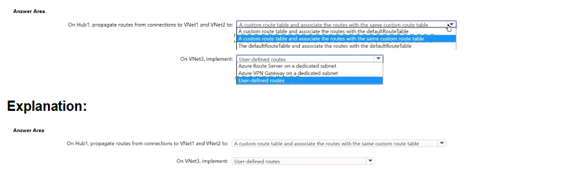
What should you do? To answer, select the appropriate options in the answer area. NOTE: Each correct selection is worth one point.


Explanation:
The setup uses Azure Virtual WAN with Hub1 connected to VNet1 and VNet2. VNet3 is peered to VNet2, which hosts NVA1 (routing appliance). BGP peering is established between NVA1 and Hub1. To enable transit connectivity from VNet1 to VNet3 (and vice versa) via Hub1 and through NVA1 for routing, routes must be propagated and associated properly in Hub1's routing configuration. The solution minimizes costs by avoiding extra gateways, firewalls, or unnecessary custom tables, leveraging default route table where possible with BGP-learned routes.

Correct Option:

On Hub1, propagate routes from connections to VNet1 and VNet2 to a custom route table and associate the routes with the same custom route table → Correct
(Note: The displayed options appear to include variations; the matching correct choice is the one using a custom route table for propagation and association of VNet1 and VNet2 connections. This allows Hub1 to learn VNet1 routes via default propagation/BGP, learn VNet3 routes from NVA1 via BGP peering, and advertise VNet3 routes back to VNet1. Using a custom route table provides granular control for transit via NVA without relying solely on default (which may not steer through NVA properly). It minimizes costs—no extra resources beyond existing NVA and BGP peering.)

On VNet3, implement: User-defined routes → Correct
In VNet3 (indirect spoke peered to VNet2), add user-defined routes (UDRs) in subnets to direct traffic destined for VNet1 (or other spokes/branches) to NVA1's IP as next hop. This ensures return/asymmetric traffic paths through the appliance for inspection/routing. No gateway or dedicated subnet is needed here, keeping costs low (only standard UDR configuration, no extra billing impact).

Incorrect Option:

On Hub1, propagate routes from connections to VNet1 and VNet2 to a custom route table and associate the routes with the defaultRouteTable → Incorrect
Associating VNet connections to the default route table while propagating to a custom table creates inconsistent routing. The hub's default route table handles standard any-to-any spoke transit natively, but for forced transit via NVA1 (BGP-learned routes), a dedicated custom route table with proper association ensures traffic from VNet1 is steered toward NVA1 for VNet3 reachability. Mixing association defeats the purpose and may cause routing loops or blackholing.

On Hub1, propagate routes from connections to VNet1 and VNet2 to the defaultRouteTable → Incorrect
Relying only on the default route table allows native spoke-to-spoke transit via Hub1 without forcing traffic through NVA1. Since the goal is transit via the NVA (for routing appliance functionality), the default table alone won't steer traffic to NVA1 for VNet3 prefixes learned via BGP. This would bypass the NVA, violating the requirement.

On VNet3, implement: Azure Route Server on a dedicated subnet → Incorrect
Azure Route Server is for dynamic BGP in non-VWAN hubs or specific scenarios; it's unnecessary here (and adds cost: ~$0.45/hour + data processing). The existing BGP peering between NVA1 and Hub1 already enables dynamic route exchange. UDRs in VNet3 suffice for next-hop control to NVA1.

On VNet3, implement: Azure VPN Gateway on a dedicated subnet → Incorrect
Deploying a VPN Gateway adds significant cost (~$0.04–$1.25/hour depending on SKU + data transfer) and complexity. It's redundant since BGP peering with Hub1 and UDRs to NVA1 provide the required transit without gateways. This violates the minimize costs requirement.

Reference:
virtual-Azure Virtual WAN

Page 3 out of 19 Pages